Design

The outstanding characteristics of GMN ball bearings are the result of technically demanding quality characteristics which achieve maximum performance limits. Various measures in design, such as preload or multiple arrangements of bearings, counter performance limitations and increase the performance capabilities of bearings.

Preloading bearings

Preload is defined as a constantly acting axial force on a ball bearing which creates an elastic deformation in the contact area of the balls and raceways.

KL_Konstruktion1_935x450px
Axial force effect on the bearing 

Performance optimization through preload

Installing ball bearings with stiff or spring preload optimizes many performance characteristics for bearing operation.

  • Reduced springing ensures the generation of a definable radial and axial rigidity (see diagram)
  • High running accuracy and workability even with changing loads
  • Reduced vibration and noise
  • Avoid slippage and friction in the rolling element contact at high speeds and high acceleration
  • Reduced sliding friction parts at high speeds (reduced contact angle change between inner and outer ring)
  • Increased load capacity (due to external loads and rotational speeds) with a long service life
KL_Konstruktion2_550x550px
Non-preloaded bearing pair 
Vorspannung_3_550x550
Preloaded bearing pair 

Rigidity

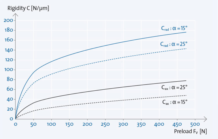
Rigidity defines the amount of axial force effect [N] on the ball bearing, which causes a shift in the bearing ring by 1 μm.

Suitable preload increases bearing rigidity and supports the load carrying capability of the bearing against operating forces.


KL_Konstruktion3_935x450px
Preload, rigidity 

Lifting force

Lifting force is the force at which the bearing becomes load-free through a central axial load on a bearing set.
If the external axial load exceeds the lifting force, …
… the balls and the raceways of the unloaded ball bearing are no longer in constant contact.
… the wear is increased by increasing sliding friction.

Spring preload

Design characteristics:

  • Bearing 1 (working side) is axially fixed in the housing, bearing 2 is arranged axially movably (fixed seat of the inner rings on the shaft)
  • The spring force on the outer ring of the bearing 2 ensures a constant preload for both bearings
  • The required spring preload is set by way of the spring travel (path-force function according to the spring characteristic curve)
  • For perfect preload results, a sufficient, axial mobility of the set outer ring on the floating bearing is required
  • The adjustment of the adjusting spring takes place in the direction of action of the external axial load
  • When using single bearings: <~>, untuned bearings can be used
  • When using bearings in tandem (<< ~ >>), bearings of the same type (L, M or S) ensure a uniform load distribution

Characteristics:

  • The preload – independent of speed and temperature – results exclusively from the spring force
  • The spring force results in an equal preload of the bearing and the thrust bearing
  • Thermal expansion of shaft and housing have no influence on preload
  • Spring-loaded bearing systems can have the highest speeds
KL_Konstruktion4_935x595px

Rigid preload individual bearings

Design characteristics:

  • Bearing 1 (working side) and bearing 2 are fixed axially and radially (fixed seating of the inner rings on the shaft or the outer rings in the housing)
  • The contact surfaces of the conversion parts on the inner and outer ring have the same length and are plane parallel
  • In order to achieve the predefined preload, a matching of the respective bearings is necessary

Characteristics:

  • Considerably higher axial as well as radial stiffness (compared to spring preload)
  • As the frictional heat increases as a result of increasing speeds, the preload increases and reduces the rotational speed limit (compared to the spring preload)
  • The theoretical speed limit can be calculated on the basis of the speed correction factors
  • Temperature differences between shaft (inner ring) and housing (outer ring) lead to preload changes due to thermal expansion
  • If the shaft has a higher temperature than the housing, the radial clearance in the bearing is reduced
  • Very high temperature differences and small contact angles can cause radial stress
  • At a small bearing distance, a temperature gradient from shaft to housing may cause an increase in the bias
  • With large bearing clearance, the temperature gradient from shaft to housing may cause a reduction in the preload
  • The change in the preload in the operating state must be taken into account during the design phase

For the complex calculation of the required bearing preload, GMN provides software solutions that deliver reliable preload results, using our long-term practical experience.

KL_Konstruktion5_935x450px

Rigid preload bearing sets

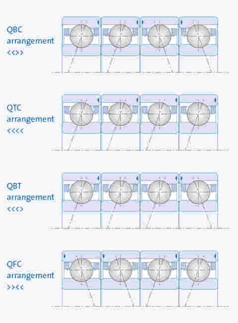
The arrangement of several bearings in so-called bearing sets increases load bearing capacity, rigidity and lifting force.

Thus the radial rigidity for all arrangements is:
at α = 15°: Crad ~ 6 · Cax
at α = 25°: Crad ~ 2 · Cax

KL_EN_KO_Lagersätze_935x550
Example: Bearing set with 3 bearings in a TBT arrangement  
KL_Konstruktion6_935x233px

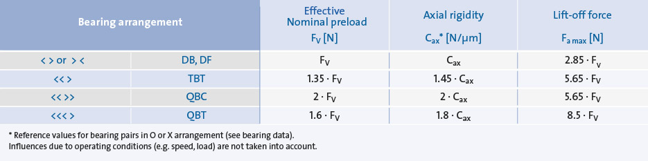
* Reference values for bearing pairs in O- or X-arrangement (see bearing data).
Operating-related influences (such as RPM, load) are not considered.

MULTIPLE ARRANGEMENT WITH 2 BEARINGS (BEARING PAIR)

With rigid bearing preload, specified bearing pairs in O, X or tandem arrangements offer an effective, cost-effective and technical solution for many applications.

O ARRANGEMENT (DB)

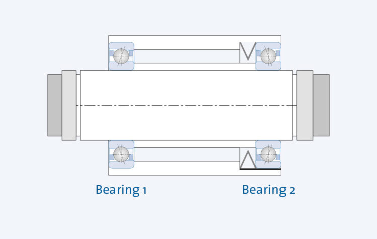
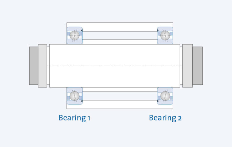
Pressure lines diverge in the direction of the bearing axis

  • Large support base (H) and high rigidity against tilting moments
  • Axial force absorption in both directions
KL_EN_KO_O-Anordnung_935x550

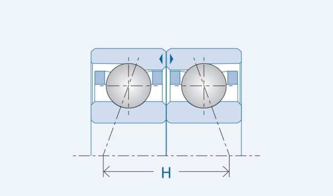
Bearing pair in O arrangement

X ARRANGEMENT (DF)

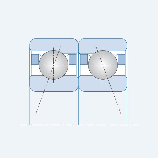
Pressure lines converge in the direction of the bearing axis

  • Insensitive to escape errors
  • Reduced support base size and tilting rigidity
  • Axial force absorption in both directions
KL_EN_KO_X-Anordnung_935x550

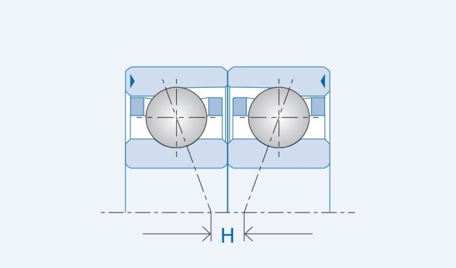
Bearing pair in X arrangement

TANDEM ARRANGEMENT (DT)

Parallel arrangement to load direction

  • Higher axial load capacity (factor 2) than single bearing
  • Both bearings have the same contact angle and are placed against a third bearing
KL_EN_KO_Tandem-Anordnung_935x550

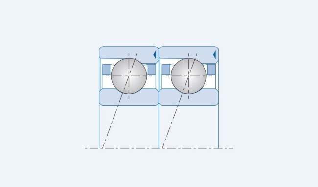
Bearing pairs in tandem

MULTIPLE ARRANGEMENT WITH 3 OR MORE BEARINGS (BEARING SET)

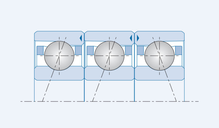
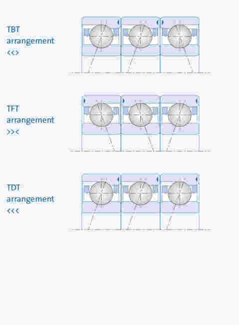
With maximum requirements for system rigidity or high loads, X, O or tandem arrangements with 3 or more bearings provide outstanding performance characteristics.

Arrangements with 3 bearings

KL_Konstruktion7_935x1268px
Bearing sets in different arrangements

Arrangement with 4 bearings

KL_Konstruktion8_935x1268px

Intermediate rings

Performance optimization through intermediate rings

One can achieve differentiated optimization of individual quality characteristics of paired bearings by installing intermediate rings (distance rings). The width of an intermediate ring is at least the width of an individual bearing.

Characteristics:

  • Increasing the support base (H) and increasing the radial rigidity
  • Optimization of heat dissipation
  • Improved bearing lubrication thanks to optimized oil feed and discharge
KL_EN_KO_Zwischenringebreite_935x550

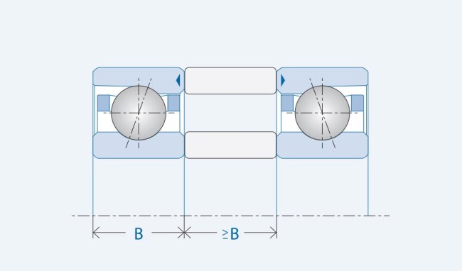
Intermediate ring width ≥ Single bearing width

Design characteristics:

  • Material: 100 Cr6, or similar, hardened (at least 45 HRC)
  • Care must be taken to ensure a good planar parallelism between the intermediate rings (see also the accuracy of the components).
  • The required parallelism of the outer and inner intermediate ring is ensured by planar grinding of both rings in one clamping operation.
  • In the case of bearing sets with intermediate rings (for example <||<||>||>), the spacer ring between the bearings is ground off with different pressure line trajectories and thus the pre-tensioning is coordinated.


KL_EN_KO_Distanzring_1220

Distance ring between different pressure line paths

Change of preload using intermediate rings

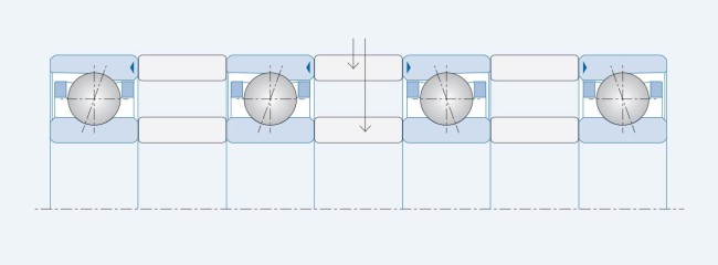
Intermediate rings provide a change to pre-tensioning for already coordinated ball bearings.
If the width of the shaft intermediate ring is less than the width of the housing…
… the preload in the O-arrangement increases
… the preload in the X array is reduced

You will find the required differential dimension of the intermediate rings for a change in the preload of a specific bearing in the technical information sheet “Change of pre-tension L-M-S” as well as further information in the download area.

Contact angle & coordination precision

Contact angle ⍺0

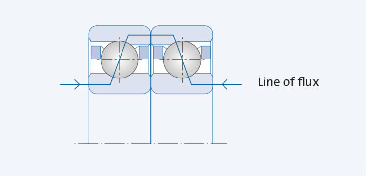
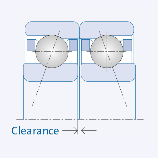
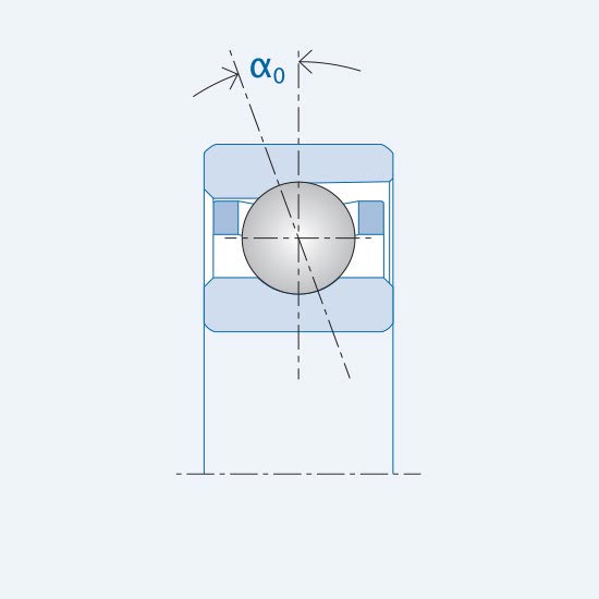
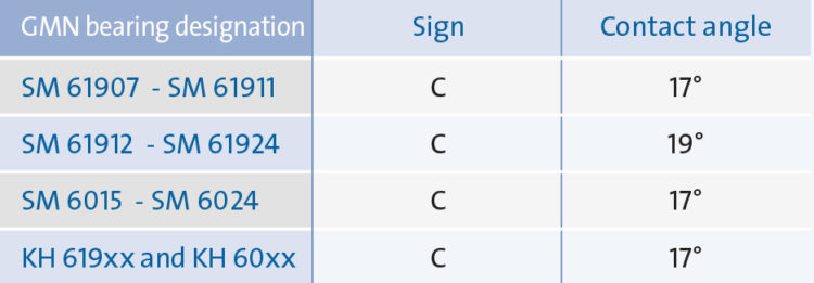
The angle of the straight lines between the contact points: Inner ring raceway – ball – outer ring raceway and the radial level defines the contact angle.

The contact angle is determined depending upon the radial bearing clearance (bearing play) and osculation of the raceways.

Load transfers between both bearing rings are made over the contact points of the raceways with the balls.

Uniform load distribution on the individual bearings in bearing arrangements sets the same contact angle on all loaded bearings.


KL_EN_KO_Winkel_935x550
Standard contact angle C (15°) and E (25°) ) 
Blindbild_2x550

The contact angle is changed depending upon operation through …

… external forces
… internal forces
(Centrifugal force of inner ring and balls at high speeds)
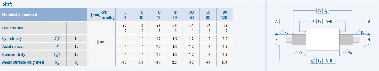
… inner ring fits
… temperature differences from inner ring to outer ring.
Deviations of the contact angle cause changes to the bearing characteristics,
which influence bearing operation.

With increasing contact angles …

… the axial rigidity increases
… the maximum permissible speed decreases
… the radial rigidity decreases

KL_Konstruktion9_935x325px
Further contact angles are available on request. 

Precision of the conversion parts

Guidance values for shaft adjustments and shape and position tolerances (DIN EN ISO 1101)

KL_Konstruktion11_1220x230_RGB
KL_Konstruktion12_1220x275RGB

Optimization of the fit with high RPMs

With increasing RPM (from about n · Dm = 1.5 . 106 mm / min.), the progressively increasing centrifugal force can cause a widening of the internal ring, and lead to functional impacts. For example:

  • Slipping of the inner ring at the contact with the shaft and at the contact surfaces
  • Frictional corrosion
  • Vibrations

 In order to counteract the lifting of the inner ring, a stronger fit is recommended.

Correction factors for an oversized bearing design and bearing series:

  • SM 60..: 1
  • SM 619..: 1.10
  • KH 60..: 1.05
  • KH 619..: 1.15
KL_Konstruktion10_935x1450Px

Valid for solid shafts. For hollow shafts (50%): Correction factor = 0.8

Tensioning bearing sets together

Performance optimization through precision nuts

The use of precision nuts to clamp bearings (sets) supports an optimal utilization of the performance capacity of GMN high-precision ball bearings.

KL_Konstruktion13_935x595Px

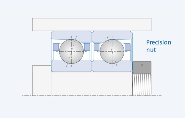
Tensioning together bearings using precision nuts

Design:

Careful installation with precision nuts prevents (interruption out, possibly follow up with a hyphen: micro-movements);
micro-movements cause contact corrosion.

  • Grind the sides of the nut at a right angle to the thread of the nut and the shaft to prevent tilting of the bearing or bending of the shaft (max 2 μm run-out tolerance)
  • Fix the precision nut on the shaft (against loosening)
  • Intermediate washers and bushes must be made parallel to the planes (max. 2 μm)

A sufficiently high axial clamping force fixes the bearings in the intended position and ensures the required preload, precision and rigidity of the bearing.

Installation:

  • Lightly lubricate the thread
  • Screw in the precision nuts with 2 to 3 times the TARGET tightening torque, then release them again and fasten them with the desired torque (compensation of temperature-dependent dimensional changes of the inner rings and seatings)
  • The required press banding of several bearings (axial) and the necessary overcoming of friction resistance when the bearings are pressed on the shaft (radial) are ensured by the 2 to 3 times primary (breakout) tightening torque
KL_Konstruktion12_1220x1195RGB

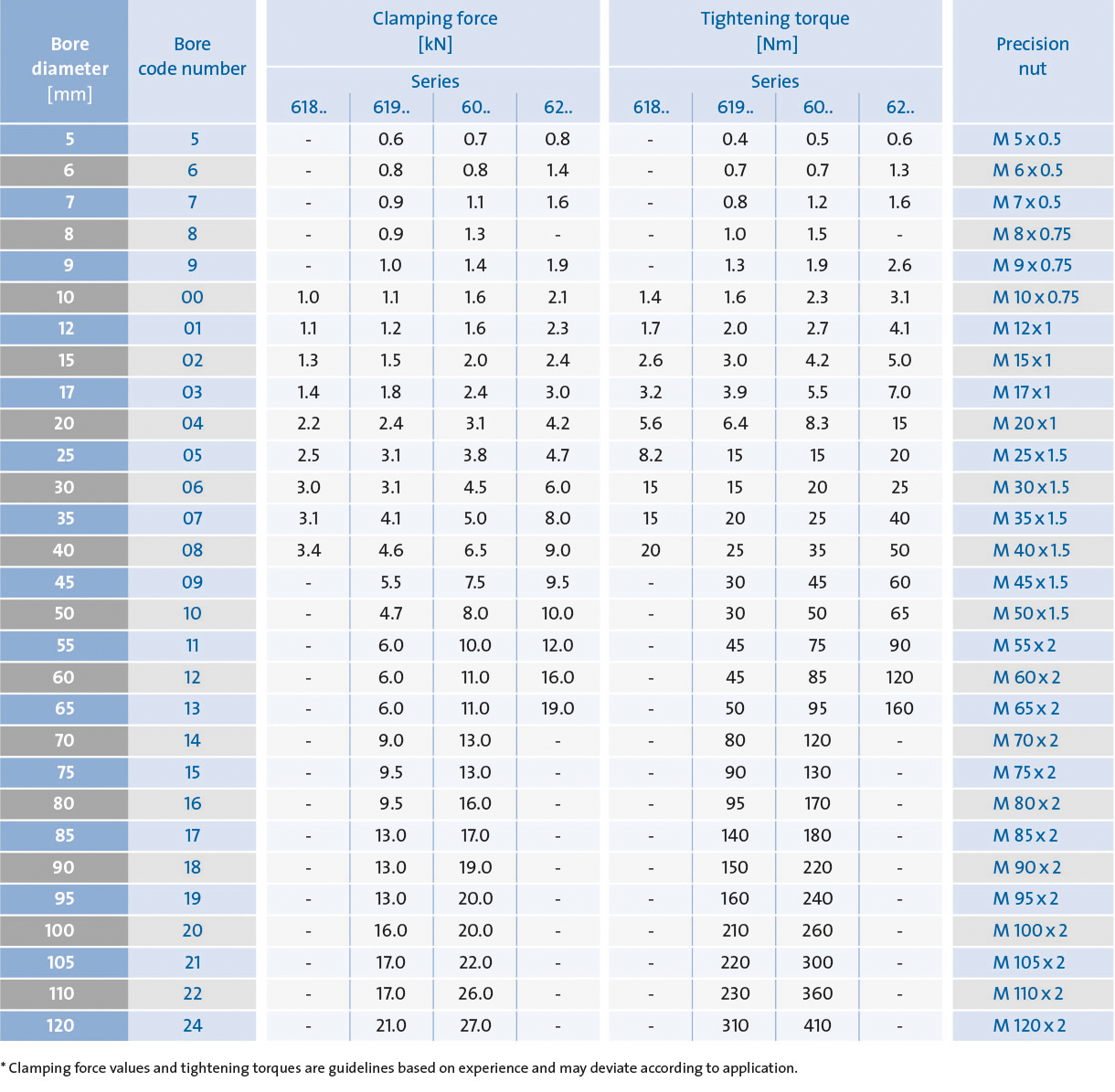
Values for clamping forces and tightening torques are experience-based indicative values and may differ depending on the application.